Ultrasonic RangeFinder
precise distance measurement and LCD display
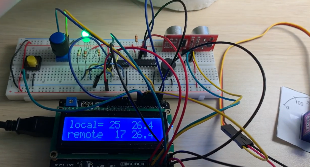
Project Overview
The Embedded Speedometer is an AVR-based microcontroller system designed to measure the speed of a moving object using an ultrasonic rangefinder. Operating on an ATmega328P microcontroller (Arduino Uno platform), the device takes sequential distance measurements, computes elapsed time using internal hardware timers, performs real-time speed calculations, and outputs the result to an LCD.
The system also features non-volatile parameter storage (EEPROM) for user settings, a rotary encoder for threshold adjustments, a passive buzzer for auditory cues, and multi-color status LEDs.
Hardware Architecture & Interfacing
The system coordinates several digital and analog peripherals, partitioned across separate driver files:
Driver Breakdown
project.c: Implements the main state machine, trigger logic, and floating-point speed computations.lcd.c/lcd.h: Drives a 16x2 character LCD via a 4-bit parallel interface to render range measurements, interval times, and menu selections.adc.c/adc.h: Interfaces with the ATmega328P's internal Successive Approximation ADC to translate analog potentiometer values into speed threshold boundaries.encoder.c/encoder.h: Decodes quadrature signals from a physical rotary encoder to increase or decrease operational limits dynamically.serial.c/serial.h: Implements basic UART serial communication protocols to transmit telemetry and receive commands from remote devices.
Technical Specifications & Timers
The most critical challenge of this project is obtaining sub-millisecond precision for both the echo pulse width and the physical interval between the two distance acquisitions. To resolve this, Timer 1 (a 16-bit timer/counter) is heavily multiplexed:
1. Distance Calculation (Ultrasonic Pulse Width)
To compute the range of an object, the rangefinder is triggered with a short 10 μs pulse, causing it to emit an ultrasonic burst. The width of the return ECHO signal is proportional to the distance of the object: Distance (cm) = Pulse Width (μs) / 58.
Timer 1 runs with a prescaler of 8 (2 MHz clock on a 16 MHz MCU core). Each timer tick equates to 0.5 μs.
- An Input Capture Interrupt (or tight pin-polling loop) captures the Timer 1 count at the rising edge (
T_start) and the falling edge (T_stop) of theECHOpulse. Pulse Width (μs) = (T_stop - T_start) × 0.5
2. Speed Computation
Once two ranges (D_1 and D_2) are logged, speed is derived: Speed (cm/s) = |D_2 - D_1| / ΔT.
Where ΔT is the elapsed time between the two range acquisitions, tracked in tenths of a second by Timer 1 overflow registers.
Firmware Implementation Details
State Machine Workflow
The software execution transitions across distinct states to ensure user safety and interface responsiveness:
INIT: Initializes DDR registers, enables global interrupts, configures Timer 1, reads the previously saved speed threshold from the EEPROM, and displays a custom splash screen.ACQUIRE_1: Instructs the ultrasonic rangefinder to perform the first distance measurement (D_1). If successful, the interval timer starts.ACQUIRE_2: Waits for the user to position the target, triggers the second measurement (D_2), and stops the interval timer to getΔT.COMPUTE: Executes speed-checking arithmetic. If the calculated speed exceeds the user-defined limit, a red LED triggers; otherwise, a green LED illuminates.ALARM: Directs a passive piezo buzzer to output a sequence of notes. An increasing pitch indicates a speed limit violation, while a decreasing pitch signals safe passage.
EEPROM Memory Mapping
To avoid losing calibrated speed thresholds during a power cycle, the system writes to the microcontroller's on-chip non-volatile EEPROM using AVR standard routines:
#include <avr/eeprom.h>

// Save threshold value to address 100
eeprom_update_byte((void *)100, current_threshold);

// Recover threshold on system startup
current_threshold = eeprom_read_byte((void *)100);